1. Introduction
Migrating model data from Tekla Structures to Autodesk products a tricky procedure due to different software behaviors of these both competitors. The only effective way is to export the IFC file from Tekla with proper exporting, mapping and import setups. A few years ago to fulfill this problem, there was .tczip export procedure involved in to manage, yet it was not reliable at all and was an unpredictable time-consuming task to get results for large size or complex geometry projects. Therefore, this article is prepared to define what should be steps to manage interconnection of the structural model data from Tekla Structures (version 2017 and onwards)(TS) to Navisworks(NW) and Revit based on experience, trial and error experiments and related software manuals which can be found online. If you, the reader, have any further idea for the more efficient way I am eager to hear it as soon as possible.
2. Tekla to Navisworks Guidelines
Step #1, Placing the model to real coordinates in Tekla Structures: Firstly, in order to let software works smooth and keep away from potential misunderstandings, I would prefer to hide unnecessary items or phases in TS. Then, the model base point should be pinned to the real position. To reach to the feature in TS click at the top left corner of the window and below capture window will be expanded. After that, go to Base points:


And another smaller window will appear (see right) to copy Project Base coordinates which are most likely defined in project documents such as BIM Manual, GIS Manual, PMP etc. Input the valid value in meters and keep sure that angle to the north also populated correctly and precise enough.
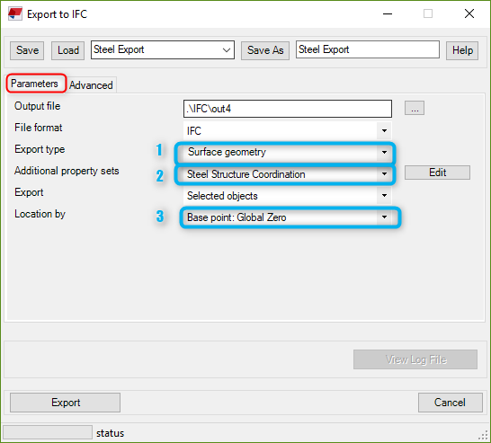
Step#2, Arranging IFC export options in Tekla Structures and exporting: After we set the project base points properly, the next step is to IFC Export settings that should be arranged as in the left and below screen shots.

Export type(1): Selecting Coordination View 1.0-2.0options cause some trouble on item geometries in Revit. Thus, to export all geometries in flawless shapes Surface geometry must be selected.

Additional property sets(2): To map the information that is desired to reflected into NW, new property sets should be generated and required parameters should be selected as in next-below capture. To reach to the window, just click Edit. Input a name in the Property Set box, I prefer to name it "Steel Structure Coordination" for this sample, as want to be read in NW.

As it can be seen in the right screenshot taken from NW properties window (flash-forward, after all conversion procedure finished), whatever we select in above capture parameters will be reflected in the NW Propertieswindow.
Location by(3): Global Zero option should be selected for NW export. We are going to use different option for Revit due to its model range issue.
Now the IFC file can be safely exported by clicking to Export button at the bottom of the Export to IFC window.
Step #3, Arranging Navisworks IFC import options and importing: Before to import IFC file to NW, keep sure that hierarchy of elements is being considered correctly by NW. Otherwise, all of items/objects are considered as parts and assembly hierarchy will be ignored. This is not the desired approach for the audit of the model, clash tests, 4D and 5D activities which are executed based on assemblies of the steel structure. Therefore, go to Options Editor>>File Readers and keep Show Spatial Hierarchy ticked, see above image. Accordingly, import/conversion can be done safely by using the Append feature of the software.

3. Tekla to Revit Guidelines
Exporting IFC model from TS to append into Revit requires slightly different procedure due to range issues occur in Revit. If the origin option is not set suitably, most probably element geometries, especially curved, inclined and small members such as bolts, will be distorted. Export option selections differ at only Step#1, rest of the steps which are defined for NW will remain the same.

Step#1, Arranging export settings for Revit in Tekla Structures and exporting: IFC model from TS should be exported with the above capture setup. Take into account that Location by setting is not the same as for NW export. Model origin should be selected as the reference.
Step#2, Preparation of Revit file which will be the host to IFC file temporarily: Revit model, whether create from scratch or use an existing one, should be opened to import IFC model that is generated in Step#1. This model will not be used but it will generate one more Revit file with structural elements in the same folder.

Before import IFC model to Revit, keep the Project Base Point visible and give values 0,0,0 for all variables as shown in the upper screenshot.
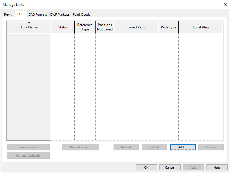
Step#3, Importing file into Revit: Import IFC model into Revit by using Manage Links and IFC segment. Importing process may take time more than expected, it is a heavy task for PC. Wait patiently and do not spend computer resources such as CPU and RAM for other tasks. And observe Revit progress information ribbon at the bottom left of the screen is it alive or crashed. End of this step you will obtain one more Revit file in the same directory. Then close the Revit file that is used for the import process, without saving.
Step#4, Realigning the model to real coordinates: As the last step, open newly generated Revit file to move to the global position of the model must be corrected as per project base point defined in the BIM documents.

4. Conclusion
All these steps may be seen complex, yet after a few attempts, it will be seen that it is not that much. Unless Autodesk merges with Trimble, incompatibility problem will exist forever on the top of the desk. In this regard, a smart control over the flow, transmitting and receiving of data is a must for a BIM Specialist.